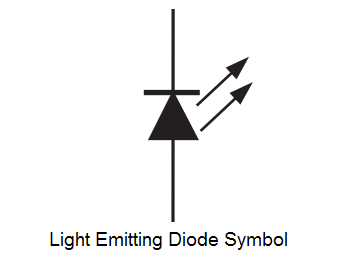
Luxus Led Schematic Symbol Polarity Bild. You may also place a k for cathode adjacent to the cathode. … leds in different shapes and designs. The way that the schematic symbol of the led maps to the physical led is shown in the diagram below
Uses include limiting the current passing through an led, and slowly charging a capacitor in a timing circuit.
The most useful electronic schematic symbols. Led is used to emit light when a current is passed through the device. How to use resistor for led and others loads. But you don't need to memorize them all. Turn the multimeter to the diode setting (usually indicated by a diode symbol), and touch. Learn vocabulary, terms and more with flashcards they have polarity, which means that they have a positive and a negative terminal and therefore you can compare the diode to a one way street. The preferred method is to place the diode schematic symbol in the silk screen. Now, your circuit is complete, and we have duplicated the circuit that is shown in the starter kit schematics, but we need to change the software. An electronic symbol is a pictogram used to represent various electrical and electronic devices or functions, such as wires, batteries, resistors, and transistors, in a schematic diagram of an electrical or electronic circuit. Schematic symbols have been standardized by two different guidelines: