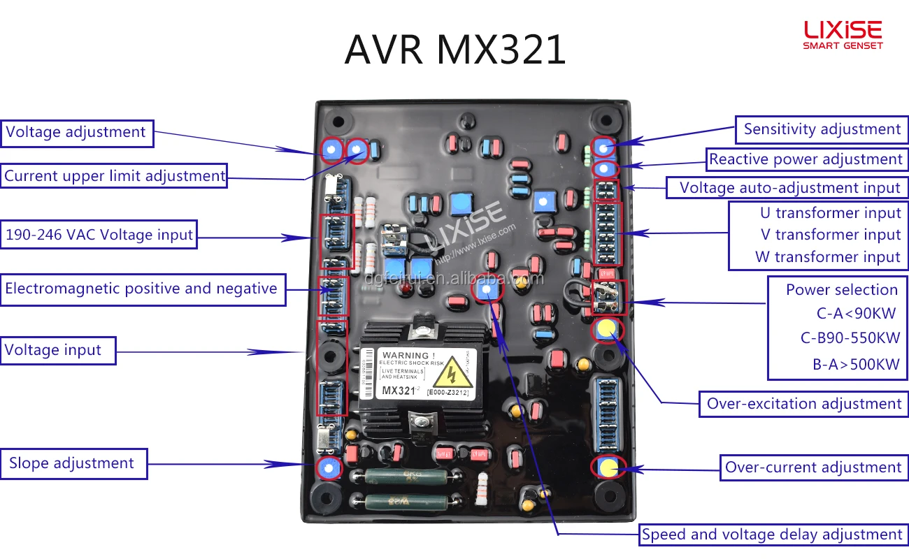
Elegantes Schematic Automatic Voltage Regulator Avr Ebenbild. Mx321 automatic voltage regulator (avr). But there are some differences to the most. Automatic voltage regulator (avr) maintains the generator terminal voltage at a given valve automatically by changing the excitation current to the generator field.

The neutral from mains enters directly in first end of dpdt and the line/phase enters the transformer primary winding which.
The regulator is equipped with a complete. Automatic voltage regulator (avr) maintains the generator terminal voltage at a given valve automatically by changing the excitation current to the generator field. The output of a2 is a square wave signal with a constant the p1 sets the trigger point of the pulse. The automatic voltage regulator works on the principle of detection of errors. If you have seen other avr schematics, you will notice that this one is quite similar in its fundamental operation. It basically steps down the input voltage to the desired level and keeps that in that same level during the supply. Continuous power conditioning and protection. Basically the avr or automatic voltage regulators function for generator is to ensure voltage generated from power generator running smooth to maintain the stable voltage in specified limit. A voltage regulator is a system designed to automatically maintain a constant voltage level. The avr supplies the required d.c.