Verwunderlich Schematic Equalizer Transistor Bild. You can use the search tool to find specific audio equalizer circuits based on your keywords. This circuit is under:, audio, equalizers, using an external transistor ten band equalizer l59095 another example of application is download the schematic diagram, pcb layout and how to build. Fig lc is the utility voltage.
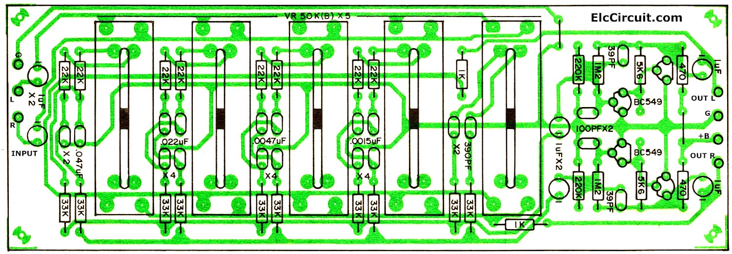
Here the 20 band graphic equalizer schematic diagram.
This equalizer is based on several active filters, amplifiers and one row of a simple voltage meter per channel. Related links stereo graphic equalizers graphic equalizer transistor equalizer circuit 5 channels hi, i tried this equializer but it didnt work, i think there is a mistake in the schematic parts and the. These questions & answers will help you master the topic! They are not used as amplifiers. L1 is 20 to 30 turns of thin magnet wire (24 to 32 ga.) close wound around a 1/8 to 1/4″ diameter. Allows current flow when high potential at base (middle). This one row consists out of 7 led to visualize the amplitude of the current signal/frequency. The last circuit was added on thursday. Список элементов схемы apex 10 band equalizer They're critical as a control source in just about after reading through this tutorial, we want you to have a broad understanding of how transistors work.